


| Motor Connecting Cables | |||
| 2YSLCY-JB/2YSLCYK-JB | 9YSLCY-JB | PENDANT CABLE |
 SHIELDED SENSOR CABLE
AppLICAtION
Smaller cables providing easier handling and space savings.
Compatible with wire-handling equipment used in harness shops.
Compatible with over-molding processes and materials used in sensor assembly.
StANDARD
Basic design to EN50264
FIRE pERFORMANCE
Flame Retardance (Single vertical wire or cable test) |
IEC 60332-1-2; EN 60332-1-2 |
|---|---|
Reduced Fire Propagation (Vertically-mounted bundled wires |
IEC 60332-3-24; EN 60332-3-24 |
Halogen Free |
IEC 60754-1; EN 50267-2-1 |
No Corrosive Gas Emission |
IEC 60754-2; EN 50267-2-2 |
Minimum Smoke Emission |
IEC 61034-2; EN 61034-2 |
CONStRuCtION
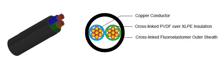
Conductor:Tinned Copper /Bare Copper.
Insulation: Cross-linked PVDF over XLPE.
Screen: Aluminum/PET Wrap+ Drain Wire.
Sheath: Cross-linked Fluoroelastomer or Cross-linked Modified Polyolefin.
Outer Sheath Option: UV resistance, hydrocarbon resistance, oil resistance, anti-rodent and anti-termite
properties can be offered as option.
COLOuR CODE
Insulation Colour: Blue,Brown,Black,White,Green(Other colours can be offered upon request).
Sheath Colour: Black (Other colours can be offered upon request).
pHYSICAL AND tHERMAL pROpERtIES
Operating temperature :-55°C—200°C.
Short-term operating temperature:
240 hours @ 175°C (Cross-linked modified polyolefin sheath);
160 hours @ 250°C(Cross-linked modified polyolefin sheath);
6 hours @ 300°C(Cross-linked fluoroelastomer sheath);
Cold bend :–40°C(Cross-linked modified polyolefin sheath);–25°C(Cross-linked fluoroelastomer sheath).
Flammability :70s(Cross-linked modified polyolefin sheath); 30s(Cross-linked fluoroelastomer sheath).
Abrasion: (ISO 6722) > 500 cycles(Cross-linked modified polyolefin sheath);> 1000 cycles(Cross-linked
fluoroelastomer sheath).
Fluid resistance: As per ISO6722:2011 (E) Media groups 1 & 2.
Bending radius: 10xOD during installation;
5xOD fixed installed.
CONStRuCtION pARAMEtERS
CONDuCtOR |
SENSOR CABLE |
|||
|---|---|---|---|---|
No.of Cores× Cross Section |
Class of Conductor |
Min. Overall Diameter |
Max. Overall Diameter |
Weight |
mm² |
|
mm |
mm |
kg/km |
2×0.35 |
2 |
3.2 |
3.6 |
20.0 |
3×0.35 |
2 |
3.4 |
3.8 |
24.8 |
2×0.50 |
2 |
3.4 |
3.8 |
24.8 |
3×0.50 |
2 |
3.6 |
4.0 |
31.0 |
2×0.75 |
2 |
3.8 |
4.2 |
33.0 |
3×0.75 |
2 |
4.1 |
4.5 |
41.7 |
2×1.0 |
2 |
4.1 |
4.5 |
40.7 |
3×1.0 |
2 |
4.4 |
4.8 |
51.8 |
Note: The parameters listed above are nominal values as per cable standards. Actual values may vary due to material and manufacturing process variations. For precise specifications or customized requirements, please contact us for further information